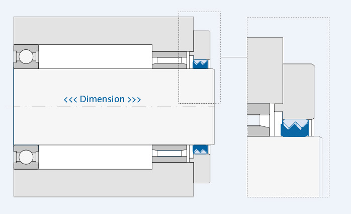
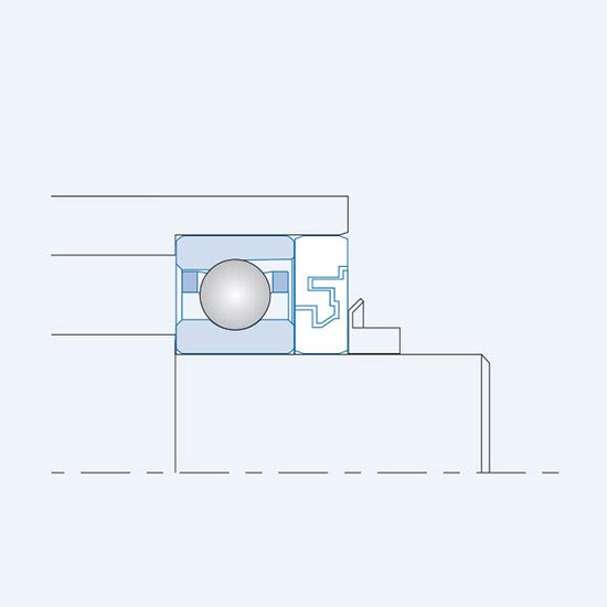
When installing a GMN non-contact seal, one must be certain that both the inner and outer ring are axially aligned. In this middle position half the amount of axial clearance is available in both directions. Because of press fit connection the races must not be secured axially by any shoulder, nut(s), and/or other restrictions from axial movement.
Operating instructions with specific installation and security information can be found in the download area.
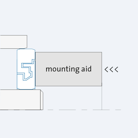
Both rings of the seal are pressed in with an installation aid (i.e. tube) together at the same time. If pressure would be applied on one ring only, the labyrinth could be destroyed.
The outer ring of L/M seals could be wider by maximum 0.1 mm than the inner ring.
![DI_Gr_Montage1_550x550[1]](https://www.gmn.de/wp-content/uploads/DI_Gr_Montage1_550x5501.jpg)
With intensive and direct impact, an additional disk can protect the sealing gap from penetrating liquids. The disk should be mounted at a sufficient distance (note the capillary forces) in front of the seal.
Adequate discharge options in front of the seal prevent a liquid backlog in front of the seal. (Liquids on the sealing gap can result in leaks.)
For non-horizontal installation positions, we are happy to offer advice on designing individual solutions to protect the sealing gap effectively from direct impact.
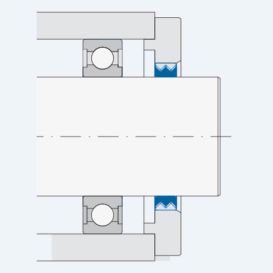
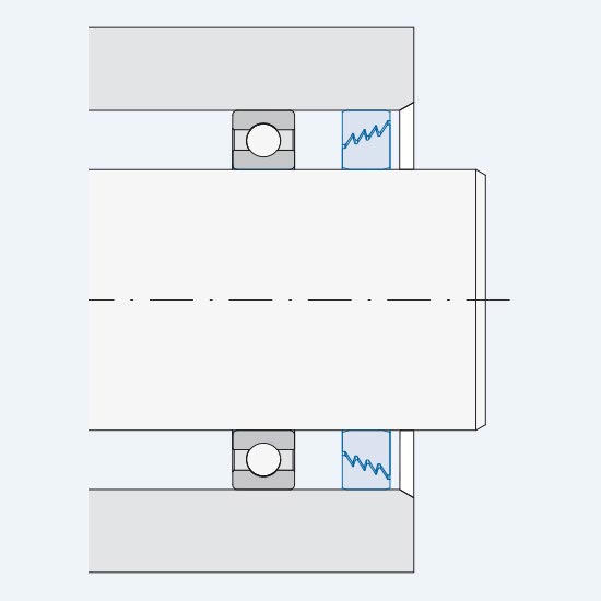
When installing the SA design, the return groove is located at the lowest point on the stationary ring.
A shaft collar for the running contact of the inner ring enables precise positioning of the seal on the stop.
For metal seals in L/M design, the outer ring is only positioned freely (without a stop).
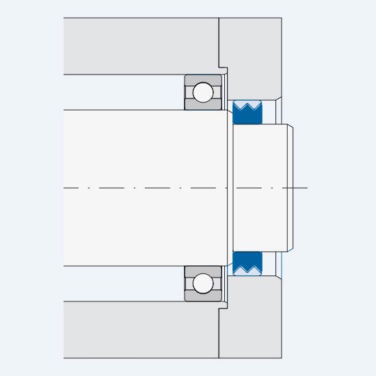

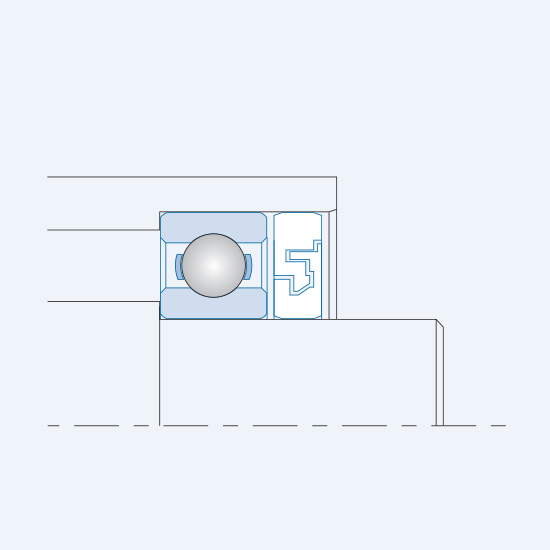
With the S/SA designs, the sealing side is oriented with the larger sealing gap diameter (e2) to the impact side.
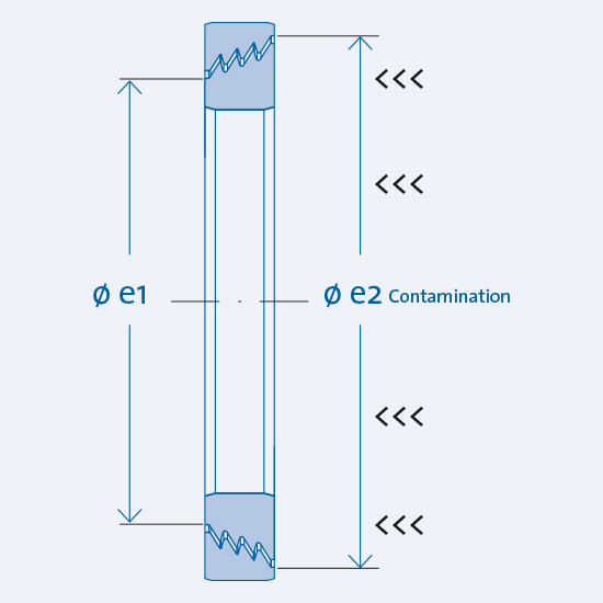
With the CF design, both rings are aligned centrally to each other and are not in contact or touching.
The larger sealing gap diameter (e2) faces the impact side.
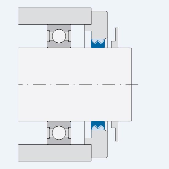
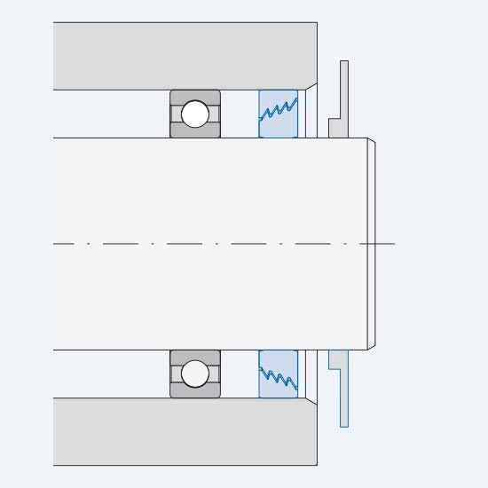
1. The GMN seal is pre-assembled onto the shaft.
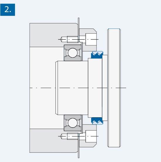
A thin metal sheet mounting aid (Thickness Sax/2, half the amount
of the seal’s axial clearance) should be interested between the housing and an additional ring.
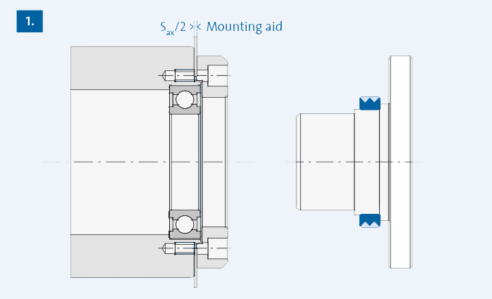
2. Shaft (with the seal) and housing (with the bearing) are fitted into each other carefully. Now the outer ring stands in the righthand end position of the seal.
3. Finally the mounting aid is removed and the screws are tightened. With this process the seal’s outer ring moves to the left by Sax/2 and finds itself in the final, correct non-contact position.
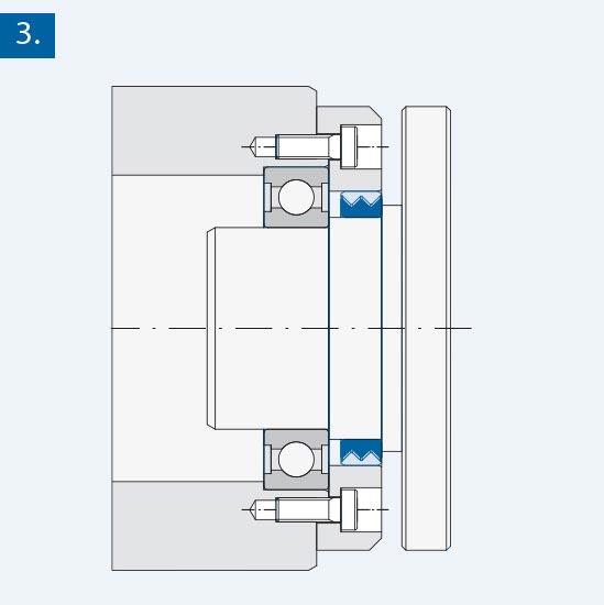
To avoid any increase of the maximum axial clearance, GMN recommends a seal with an increased axial clearance or an asymmetrical seal adjustment in the extension direction. (The excess of maximum axial clearance could destroy the seal.)