GMN labyrinth seals are divided into 3 models. The models CF, L/M and S/SA differ in material, gap height, labyrinth and function.
Non-contact seals from GMN are made from different materials:
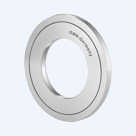
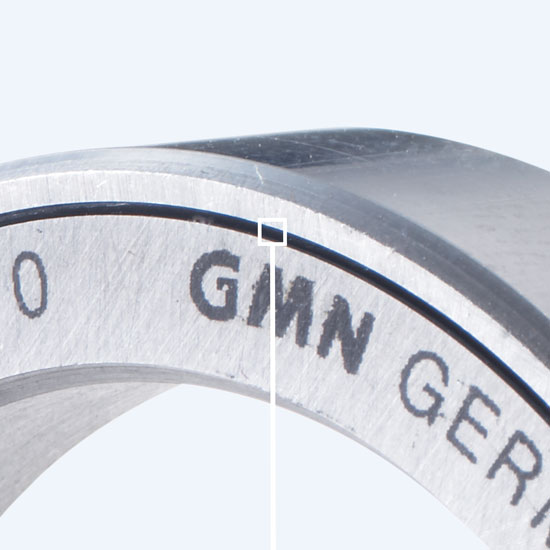
GMN labyrinth metal seals in CF design are made from an inner and an outer ring. The two rings create a labyrinth geometry made up of a sequence of radial and horizontal gaps. A retaining ring connects the two rings to form a non-disintegrating unit and also creates a catching groove at the end of the labyrinth.
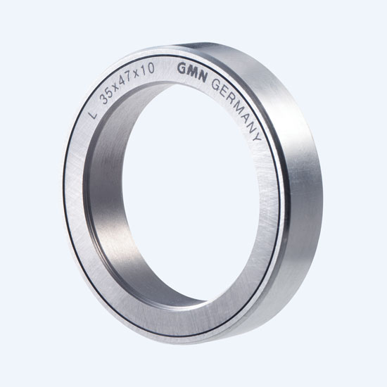
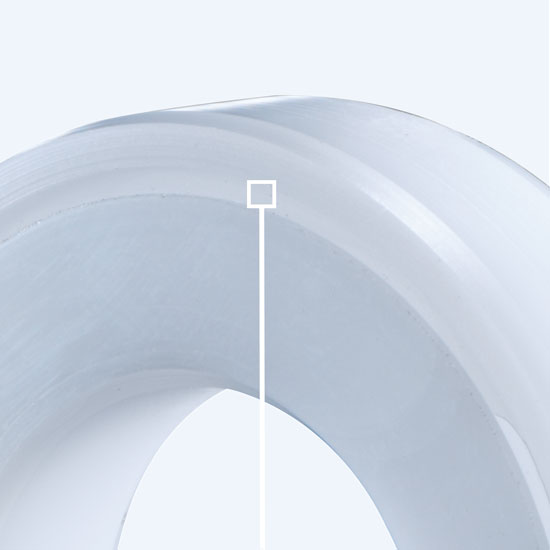
GMN labyrinth metal seals in L/M design consist of two metal materials with different strengths. In a special manufacturing process, a narrow, horizontal gap is created between an inner ring made from steel and an outer ring made from aluminum along a labyrinth geometry.
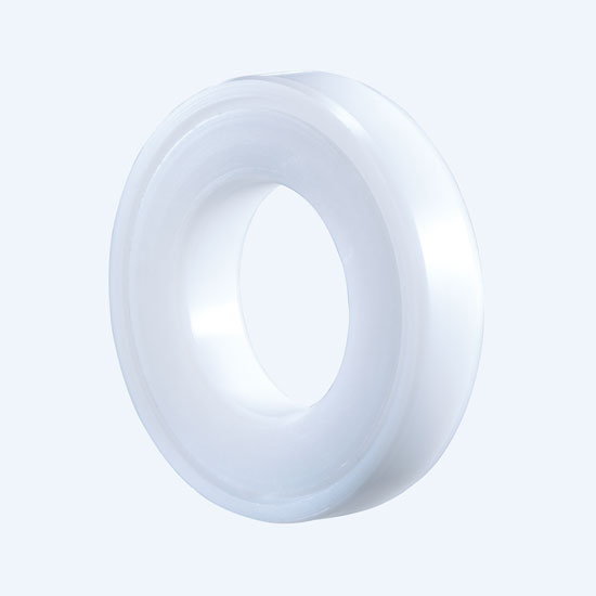
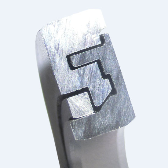
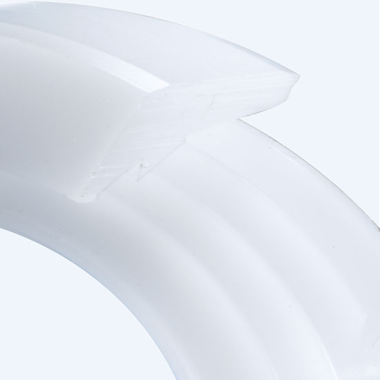
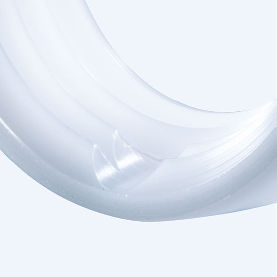
With GMN labyrinth plastic seals in S/SA design, the inner and outer ring are made from the same material. In contrast to the L/M design, the gap along the labyrinth geometry is tapered.
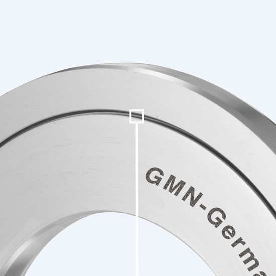
The theory of non-contact seals is based on the gap height between inner and outer rings. The tighter the gap height is on the seal (reduction in ring gap area), diminishes the opportunity for any contaminant entry.
Depending on amount, direction and speed (intensity) of the contamination, an additional protection against direct splashing liquids is recommended. As an additional supporting effect inherent in a non-contact seal, tight gaps create an air cushion inside the gap. This air cushion increases in correlation to rotational speed.
GMN labyrinth metal seals in CF design have a constant gap height of 0.25 mm on the horizontal gaps. The radial gaps are wider to support the back flow effect.
GMN labyrinth metal seals in L/M design achieve maximum effectiveness due to a constant low gap height along the entire labyrinth geometry of 0.2–0.5 mm (depending on the size).
GMN labyrinth plastic seals in S/SA design have different gap heights due to their asymmetrical labyrinth geometry. The minimal gap height of approx. 0.5 mm guarantees maximum effectiveness, including the field of plastic solutions.
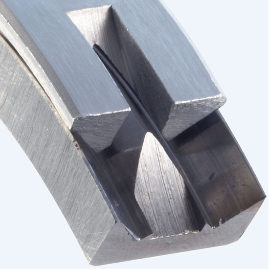
The labyrinth geometry acts as a barrier against any liquids or dust. Particles entering the labyrinth seal bump against the labyrinth, therefore any media is slowed. The shifts in direction inside the labyrinth make passing the seal almost impossible.
GMN labyrinth metal seals in CF design have a profile consisting of an optimized sequence of axial and radial gaps. Radial gaps create a backflow effect due to the centrifugal force when the shaft is rotating. Narrow axial gaps make the flow more difficult using capillary forces. Finally, a catching groove at the end of the profile ensures absolute leak-tightness – even when the shaft is at a standstill!
GMN labyrinth metal seals in L/M design achieve 1–4-layered labyrinths in extremely tight spaces (depending on the size). A special manufacturing process guarantees 100% labyrinth geometry conformity between the outer and the inner ring.
GMN labyrinth plastic seals in S/SA design have 2–4-layered labyrinths. In this design, the tapered run of the labyrinth optimizes the sealing effect using the centrifugal force. Penetrated media is transported to the large gap diameter through rotation. The larger gap diameter is mounted facing the impact side.
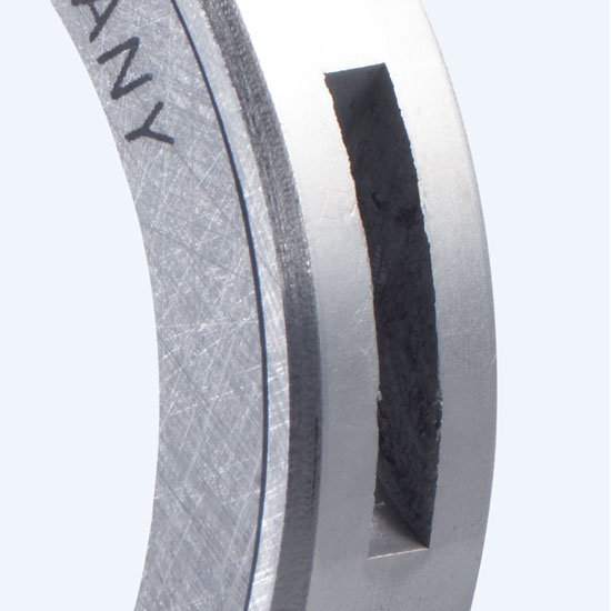
In case of heavy splashing liquids, type M and SA with drain grooves are preferred.
The sealing gap is protected against direct impact with an adapted surrounding structure. The design of the input area in particular has a significant impact on the effectiveness of the seal.
An adequately sized drainage system catches returned liquid and discharges it reliably.
The narrow sealing gap slows the flow and minimizes fouling penetration. The labyrinth geometry creates an effective barrier against liquid and dust particles.
In the event of increased impact, drainage grooves on the outer ring (“SA” and “M” designs) return any penetrated liquids in the connecting part via a ring groove.