This page contains general installation instructions for quick and easy installation of GMN sprag type freewheel clutches.
Operating instructions with specific installation and security information can be found in the download area.
All GMN freewheel clutch insert elements with rings can be installed for a left or right clamping direction.
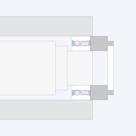
GMN complete freewheel clutch units with press fit on the outer ring or/and on the inner ring are pressed in or on using an installation aid (tube or connector). The force of a hand press is usually sufficient for the installation.
Caution: For complete freewheel units with integrated bearing, the press fit pressure must not be applied by the balls. The inner ring and outer ring must be pressed in at the same time.

GMN freewheel clutch insert elements are built symmetrically and can be installed for a left or right clamping direction. All freewheel clutch insert elements are delivered on a packaging tube to protect them against damage. This tube can also be used as an installation aid.
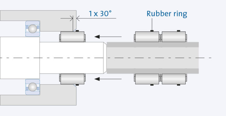
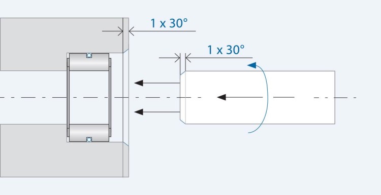
If possible, mating parts should be chamfered to improve installation: installation chamfer for shaft and housing: 1 x 30°
As an additional protective measure for the spragtype freewheel clutch, a rubber ring is stretched around the freewheel clutch insert element of type series FE 400 M.
Installation is performed by pushing the freewheel directly from the packing tube onto the shaft and into the hub. The freewheel can be completely pushed in after the rubber ring has been removed.
The freewheel clutch is first positioned in the hub, the chamfered shaft can then be inserted with a turning motion in the idle direction.
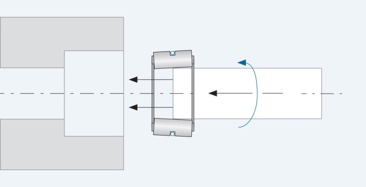
If the shaft is not chamfered, the freewheel clutch insert element should be pushed halfway onto the end of the shaft so that the sprag are slightly tilted. This reduces the outer diameter of the freewheel clutch insert element enough to allow the shaft to be inserted together with the freewheel with a turning motion in the idle direction.